Replacing USB Camera Cables
Replacing USB Cables
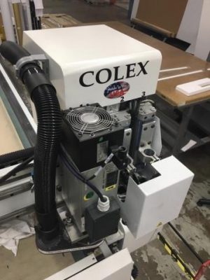
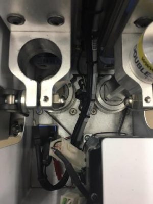
1. Please position the machine’s head to the spot where it’s convenient to take off the head cover, the X1 motor cover and W motor cover. Disconnect the bumper plugs and motor power plugs to move the bridge and the head of the machine manually.
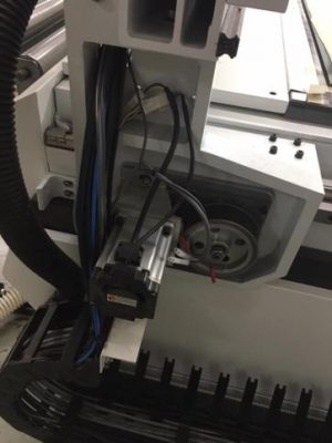
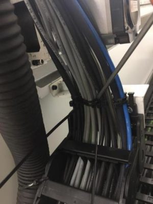
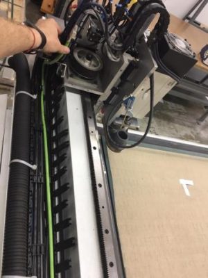
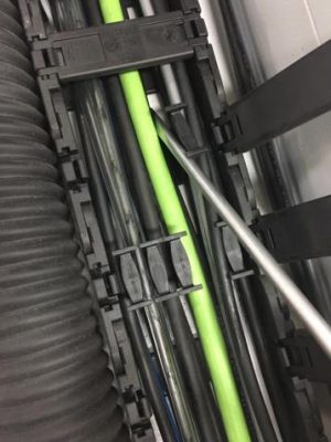
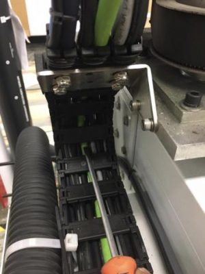
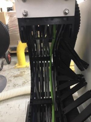
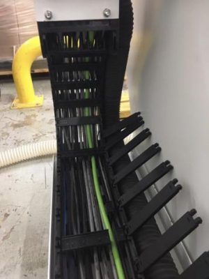
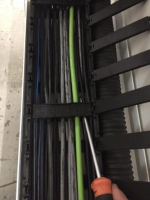
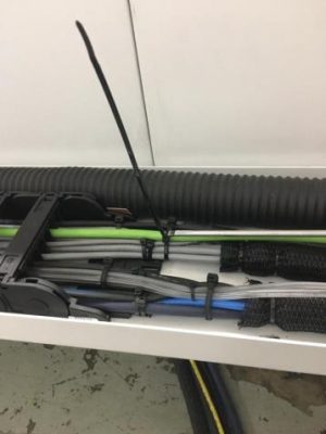
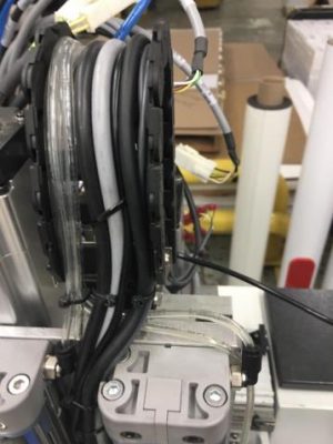
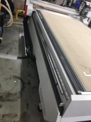
2. Move the bridge towards the back of the table and the head towards the right side to make the cable trays as “flat” as possible and open them with a flat screwdriver.
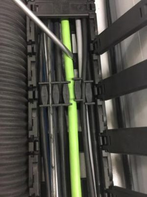
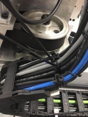
3. Cut the necessary zip-ties on the Y and X plastic cable trays fingers and shift the cable dividers one section forward or backward.
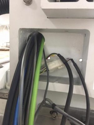
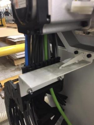
4. Run one end of the Ethernet cable through the opening in the X1 motor bridge bracket towards the head of the machine.
Spread the cables in the opening for additional space if necessary.
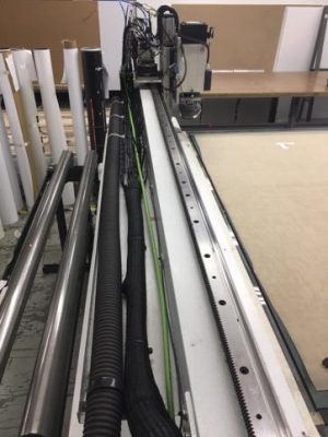
5. Place the Ethernet cable next to Y axis cable tray. Pull it towards the machine’s head. It should be long enough to reach the camera extension cable. The Ethernet cable plug needs to be placed close to the cables to prevent the unnecessary vibration.
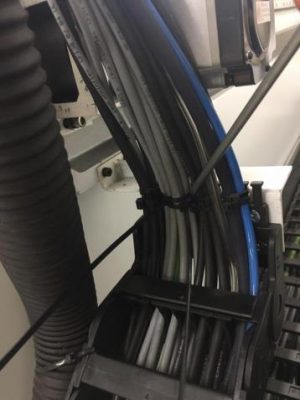
6. Place the Ethernet cable into second or third spot on Y cable tray.
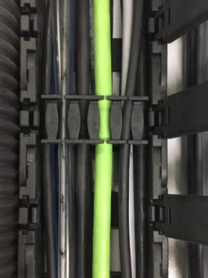
7. Put the dividers back to their original spots and close all sections of Y axis cable chain.
8. Use the zip-ties to secure the placement of the Ethernet cable. Don’t make them tight yet.
9. Leave some slack for the cables inside of the plastic cable trays before tightening zip-ties up at both ends of the Y axis cable chain.
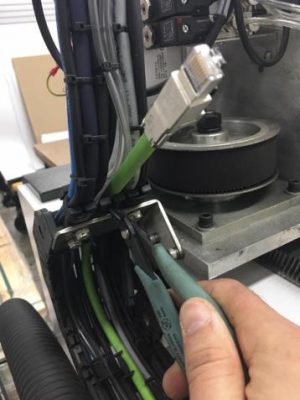
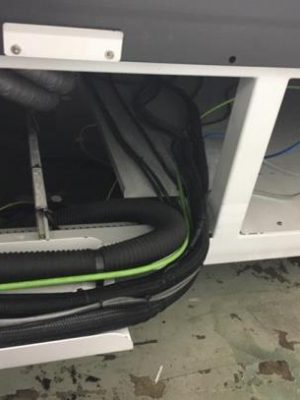
10. Fish the cable through the X axis cable chain. Move the cable dividers the same way like you did for Y axis cable tray.
11. Place the cable into the space between the first and second dividers.
12. Make sure not to pinch any cables while placing the dividers back to their original positions.
13. Use the zip-ties to secure the placement of the Ethernet cable. Don’t make them tight yet.
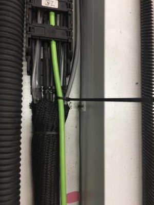
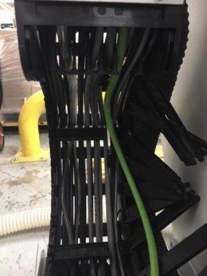
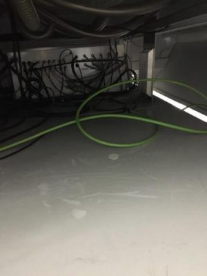
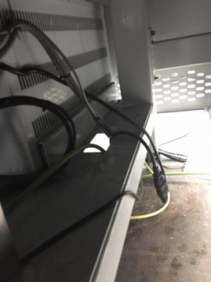
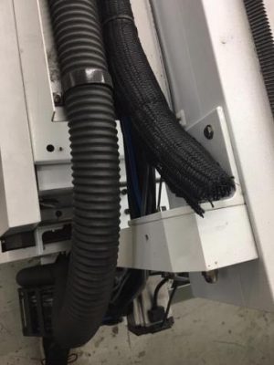
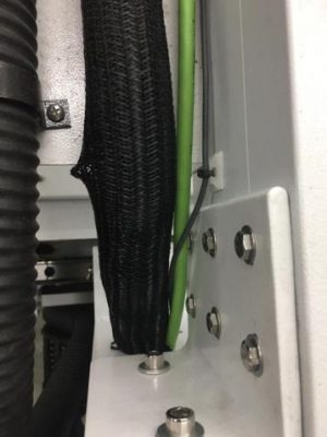
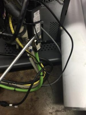
14. Fish the cable towards the PC station as shown in the photos.
15. Make sure cable is long enough to reach PC.
16. Secure the Ethernet cable next to the electrical panel to prevent pinching of the cable when working with the electrical box.
17. Adjust mesh cable wrap.
18. Leave some slack in X cable tray, tighten all zip-ties at the ends of trays and cut their tails off.
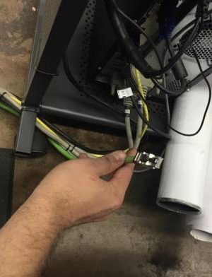
19. Secure the ethernet cable in the area between the machine and the PC station.
20. Attach the new cable to the db37 cables with the zip-ties.
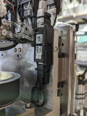
21. Install the Ethernet to the USB adapter/transmitter at the PC end.
22. Plug 1’ USB extension cables into both the adapter and PC ports.
21. Install the 6’ USB to mini-USB extension. Plug the mini USB end into the camera. Leave some slack so you can unplug it if necessary.
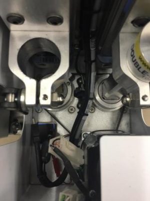
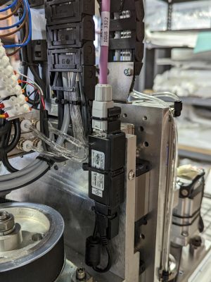
23. Open the Z plastic cable chain and run the cable towards the back of the machine head. Secure the new cable attaching it the the other cables already installed. Use the provided zip-ties for it.
24. Avoid pinching points.
25. Plug the Ethernet cable into the Ethernet-to-USB adapter/transmitter.
26. Plug in the 6’ USB extension cable into the adapter and cut off all of the zip-ties tails.
27. If everything is installed properly both Ethernet-to-USB adapters/transmitters should have a light on.
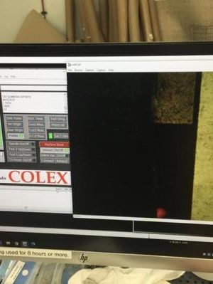
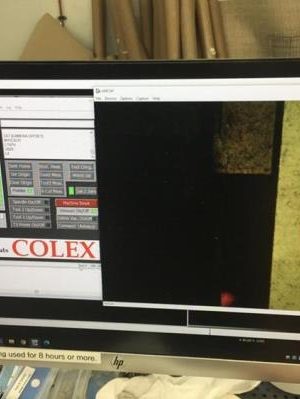
28. Activate the camera using Optiscout/Colex Cut Center or AmCap software. You should see the camera view. Move the machine to double check that it works properly.
29. If camera is ON both Ethernet-to-USB adapters/transmitter should start blinking (several times per second).
30. Install all covers back on.

